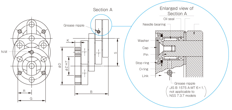
These are couplings with different shaft centers that use the crank motion of a link. Power input at one end disc is transmitted via a link and center disc to another end disc.The amount of eccentricity is determined by the length of the link. Power can be transmitted smoothly when shaft centers are different. And since power is transmitted by the crank motion of the link, translation of shaft centers during rotation is possible. The standard NSS model has 3 x 2 links, while quasi-standard NSS models increase the number of links and the rated torque.
Features
Specifications
Structure and Materials
Downloads
Translation of shafts is possible
Since the crank motion of the link is used, the drive and driven shafts can be translated freely within the displacement range even when stopped or rotating under load.
Space saving
Couplings can be shortened in the axial direction and a larger amount of displacement achieved compared to the older combination of universal joint and spline.
NSS Models
[Specifications]
Model | No. of links | Parallel misalignment | Torque | Max. rotation speed [min-1] | Bearing basic load [N] | Pin pitch = Radius of the circle [m] | Moment of inertia [kg・m2] | Mass [kg] | |||
---|---|---|---|---|---|---|---|---|---|---|---|
Min. [mm]. S×0.25 [mm] | Max. [mm] S×0.95 [mm] | Linear Max. [mm] | Nominal [N・m] | Max. [N・m] | C | R | |||||
NSS 7.3.7 | 3×2 | 9 | 34 | 65 | 49 | 137 | 3000 | 3870 | 0.024 | 9.03×10⁻⁴ | 1.3 |
NSS 7.7.9 | 3×2 | 18 | 66 | 128 | 68 | 196 | 2500 | 3870 | 0.035 | 2.69×10⁻³ | 1.9 |
NSS 10.9.12 | 3×2 | 23 | 85 | 165 | 196 | 600 | 2000 | 8920 | 0.045 | 1.15×10⁻² | 4.9 |
NSS 13.9.14 | 3×2 | 23 | 85 | 165 | 350 | 1060 | 1800 | 14120 | 0.050 | 2.80×10⁻² | 10.4 |
NSS 16.10.16 | 3×2 | 25 | 95 | 183 | 640 | 1850 | 1500 | 21570 | 0.057 | 5.80×10⁻² | 15.7 |
NSS 20.9.20 | 3×2 | 23 | 85 | 165 | 1180 | 3470 | 1000 | 30890 | 0.075 | 1.61×10⁻¹ | 27 |
NSS 20.9.20/4 | 4×2 | 23 | 85 | 165 | 1370 | 4170 | 600 | 30890 | 0.075 | 1.80×10⁻¹ | 30 |
NSS 20.9.23/5 | 5×2 | 23 | 85 | 165 | 2060 | 6280 | 500 | 30890 | 0.090 | 3.08×10⁻¹ | 35 |
NSS 20.9.25/6 | 6×2 | 23 | 85 | 165 | 2750 | 8340 | 460 | 30890 | 0.100 | 4.48×10⁻¹ | 43 |
NSS 20.9.33/8 | 8×2 | 23 | 85 | 165 | 5200 | 15700 | 300 | 30890 | 0.140 | 1.19 | 59 |
NSS 20.9.39/10 | 10×2 | 23 | 85 | 165 | 7850 | 23500 | 250 | 30890 | 0.170 | 2.25 | 79 |
*If the number of links is not 3 × 2, the part must be made to order.
*Max. rotation speed does not take into account dynamic balance.
*Select NSS model SCHMIDT couplings as guided by the design checklist on P.96-99, with due consideration to service life.
[Dimensions]

Model | D | B | S | Z | G | N | M | K |
---|---|---|---|---|---|---|---|---|
NSS 7.3.7 | 70 | 74 | 36 | 25 | 48 | 3 | M10 | 10 |
NSS 7.7.9 | 92 | 74 | 70 | 45 | 70 | 3 | M10 | 10 |
NSS 10.9.12 | 120 | 101 | 90 | 50 | 90 | 3 | M12 | 15 |
NSS 13.9.14 | 140 | 134 | 90 | 55 | 100 | 3 | M16 | 22 |
NSS 16.10.16 | 160 | 155 | 100 | 60 | 115 | 3 | M16 | 25 |
NSS 20.9.20 | 200 | 196 | 90 | 80 | 150 | 3 | M20 | 30 |
NSS 20.9.20/4 | 200 | 196 | 90 | 80 | 150 | 4 | M20 | 30 |
NSS 20.9.23/5 | 230 | 196 | 90 | 120 | 180 | 5 | M20 | 30 |
NSS 20.9.25/6 | 250 | 196 | 90 | 120 | 200 | 6 | M20 | 30 |
NSS 20.9.33/8 | 330 | 196 | 90 | 210 | 280 | 8 | M20 | 30 |
NSS 20.9.39/10 | 390 | 196 | 90 | 250 | 340 | 10 | M20 | 30 |

NSS
