
These are open-mounted clutches and brakes that have through-shaft constructions of clutch and brake outside a light alloy drum.Power is output from the input hub continuously to the output shaft. The output shaft is braked when clutch current is shut off and the brake is energized in response. The construction holds up well under radial loads due to a wide bearing span, so it can be used under high tension when mounted with V pulleys, spur gears or the like. Thanks to the through-shaft construction, output is available at both ends of the shaft, so many mechanism layouts are possible, including using both ends in split driving or mounting a detection disc or the like on one end.
121 (20G) Types
[Specifications]
| Model | Size | Dynamic friction torque Td [N・m] | Static friction torque Ts [N・m] | Coil (at 20℃) | Heat resistance class | Max. rotation speed [min-1] | Rotating part moment of inertia J [kg・m2] | Total work performed until readjustment of the air gap ET [J] | Armature pull-in time ta [s] | Torque build-up time tp [s] | Torque decaying time td [s] | Mass [kg] | |||
|---|---|---|---|---|---|---|---|---|---|---|---|---|---|---|---|
| Voltage [V] | Wattage [W] | Current [A] | Resistance [Ω] | ||||||||||||
| 121-06-20G | 06 | 5 | 5.5 | 24 DC | 11 | 0.46 | 52 | B | 3000 | 1.43×10⁻⁴ | 36×106 | C: 0.020/B: 0.015 | C: 0.041/B: 0.033 | C: 0.020/B: 0.015 | 1.5 |
| 121-08-20G | 08 | 10 | 11 | 24 DC | 15 | 0.63 | 38 | B | 3000 | 4.23×10⁻⁴ | 60×106 | C: 0.023/B: 0.016 | C: 0.051/B: 0.042 | C: 0.030/B: 0.025 | 2.7 |
| 121-10-20G | 10 | 20 | 22 | 24 DC | 20 | 0.83 | 29 | B | 3000 | 1.42×10⁻³ | 130×106 | C: 0.025/B: 0.018 | C: 0.063/B: 0.056 | C: 0.050/B: 0.030 | 5.5 |
| 121-12-20G | 12 | 40 | 45 | 24 DC | 25 | 1.04 | 23 | B | 3000 | 4.18×10⁻³ | 250×106 | C: 0.040/B: 0.027 | C: 0.115/B: 0.090 | C: 0.065/B: 0.050 | 9.6 |
| 121-16-20G | 16 | 80 | 90 | 24 DC | 35 | 1.46 | 16 | B | 3000 | 1.34×10⁻² | 470×106 | C: 0.050/B: 0.035 | C: 0.160/B: 0.127 | C: 0.085/B: 0.055 | 18.5 |
| 121-20-20G | 20 | 160 | 175 | 24 DC | 45 | 1.88 | 13 | B | 2500 | 4.13×10⁻² | 10×108 | C: 0.090/B: 0.065 | C: 0.250/B: 0.200 | C: 0.130/B: 0.070 | 35 |
| 121-25-20G | 25 | 320 | 350 | 24 DC | 60 | 2.50 | 9.6 | B | 2000 | 1.02×10⁻¹ | 20×108 | C: 0.115/B: 0.085 | C: 0.335/B: 0.275 | C: 0.210/B: 0.125 | 64 |
*The dynamic friction torque, Td, is measured at a relative speed of 100 min-1. Depending on the initial torque characteristics, break-in to condition the engaging surfaces may also be required.
[Dimensions]
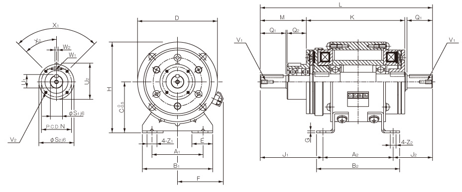
| Size | Dimensions of part | Dimensions of shaft | |||||||||||||||||||||||||||
|---|---|---|---|---|---|---|---|---|---|---|---|---|---|---|---|---|---|---|---|---|---|---|---|---|---|---|---|---|---|
| A1 | A2 | B1 | B2 | C | D | E | F | G | H | J1 | J2 | K | L | M | N | Z1 | Z2 | Q1 | Q2 | S1 | S2 | U1 | U2 | V1 | V2 | X1 | X2 | W1, 2 | |
| 6 | 52.5 | 75 | 80 | 90 | 55 | 80 | 27.5 | 53 | 2.6 | 95 | 65.5 | 40.5 | 105.5 | 181 | 47 | 33 | 13.5 | 6.5 | 25 | 20 | 11 | 38 | 12.5 | 39.5 | M4×0.7, length: 8 | 3-M4×0.7, length: 4 | 3-120° | 60° | 4 |
| 8 | 65 | 90 | 90 | 105 | 65 | 100 | 27.5 | 61 | 2.6 | 115 | 78.5 | 48.5 | 126.5 | 217 | 57 | 37 | 13.5 | 6.5 | 30 | 25 | 14 | 45 | 16 | 47 | M4×0.7, length: 8 | 3-M4×0.7, length: 6 | 3-120° | 60° | 5 |
| 10 | 80 | 110 | 110 | 130 | 80 | 125 | 32.5 | 72 | 3.2 | 142.5 | 98 | 62 | 154 | 270 | 72 | 47 | 15.5 | 9 | 40 | 30 | 19 | 55 | 21 | 57 | M6×1, length: 11 | 4-M4×0.7, length: 8 | 4-90° | 45° | 5 |
| 12 | 105 | 135 | 140 | 160 | 90 | 150 | 35 | 81 | 3.2 | 165 | 121 | 73.5 | 184 | 330 | 92 | 52 | 20 | 11.5 | 50 | 40 | 24 | 64 | 27 | 67 | M6×1, length: 11 | 4-M4×0.7, length: 8 | 4-90° | 45° | 7 |
| 16 | 135 | 160 | 175 | 185 | 112 | 190 | 43 | 97 | 4.5 | 207 | 149 | 90 | 221 | 399 | 113 | 62 | 24.5 | 11.5 | 60 | 50 | 28 | 75 | 31 | 78 | M6×1, length: 11 | 6-M5×0.8, length: 8 | 6-60° | 30° | 7 |
| 20 | 155 | 200 | 200 | 230 | 132 | 230 | 45 | 109 | 6 | 247 | 187 | 117 | 276 | 504 | 142 | 74.5 | 28 | 14 | 80 | 60 | 38 | 90 | 41.5 | 93.5 | M10×1.5, length: 17 | 4-M6×1, length: 12 | 4-90° | 45° | 10 |
| 25 | 195 | 240 | 240 | 270 | 160 | 290 | 47.5 | 124 | 20 | 305 | 238 | 154 | 334 | 632 | 183 | 101.5 | 28 | 14 | 110 | 70 | 42 | 115 | 45.5 | 118.5 | M10×1.5, length: 17 | 8-M6×1, length: 12 | 8-45° | 22.5° | 12 |
*The input/output shaft keyways are old JIS standard class 2 while the key is old JIS standard class 1. Note that the keyway dimensions of the unit hub part do not conform to JIS standards. Check them on the dimensions table above.
*When inserting pulleys or the like onto input/output shafts, use the supplied insertion set.
*The 121-25-20G base is a casting.
