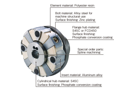
Excellent environmental resistance
In addition to absorbing vibration and shock, they have excellent resistance to cold, heat, and oil, enabling their use in punishing environments.
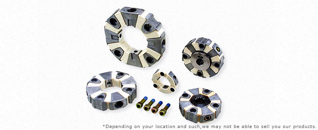
Clamping hubs
When coupling a spline shaft (pump shaft) and cylinder hub, a clamping hub can be provided to allow complete locking in place by means of center lock action. We can design to meet your needs, so please contact us for details.
CF-H (O0/O1/O2) Types
[Specifications]
| Model | Torque | Misalignment | Max. rotation speed [min-1] | Dynamic torsional stiffness [N・m/rad] | |||
|---|---|---|---|---|---|---|---|
| Nominal [N・m] | Max. [N・m] | Parallel [mm] | Angular [°] | Axial [mm] | |||
| CF-H-008 | 100 | 200 | 0.3 | 0.5 | ± 3 | 6500 | 1.27×10⁴ |
| CF-H-016 | 200 | 400 | 0.3 | 0.5 | ± 3 | 5500 | 2.46×10⁴ |
| CF-H-030 | 400 | 800 | 0.4 | 0.5 | ± 3 | 4000 | 5.91×10⁴ |
| CF-H-040 | 600 | 1200 | 0.4 | 0.5 | ± 3 | 4000 | 1.87×10⁵ |
| CF-H-050 | 800 | 1600 | 0.4 | 0.5 | ± 3 | 4000 | 1.91×10⁵ |
| CF-H-090 | 950 | 1900 | 0.4 | 0.5 | ± 3 | 4000 | 2.69×10⁵ |
| CF-H-110 | 1100 | 2200 | 0.4 | 0.5 | ± 3 | 4000 | 2.79×10⁵ |
| CF-H-160 | 1600 | 3200 | 0.4 | 0.5 | ± 3 | 3600 | 5.11×10⁵ |
| CF-H-240 | 2500 | 5000 | 0.4 | 0.5 | ± 3 | 3000 | 5.10×10⁵ |
| Model | Moment of inertia [kg・m2] | Mass [kg] |
|---|---|---|
| CF-H-008-O0 | 9.4×10⁻⁴ | 0.4 |
| CF-H-016-O0 | 3.0×10⁻³ | 0.8 |
| CF-H-030-O0 | 9.2×10⁻³ | 1.5 |
| CF-H-040-O0 | 6.9×10⁻³ | 1.4 |
| CF-H-050-O0 | 1.2×10⁻² | 1.8 |
| CF-H-090-O0 | 1.5×10⁻² | 2.3 |
| CF-H-110-O0 | 2.3×10⁻² | 2.8 |
| CF-H-160-O0 | 3.6×10⁻² | 3.4 |
| CF-H-240-O0 | 0.10 | 5.8 |
| Model | Moment of inertia [kg・m2] | Mass [kg] |
|---|---|---|
| CF-H-008-O1 | 1.8×10⁻³ | 1.3 |
| CF-H-016-O1 | 4.9×10⁻³ | 2.5 |
| CF-H-030-O1 | 1.9×10⁻² | 6.0 |
| CF-H-040-O1 | 1.3×10⁻² | 4.4 |
| CF-H-050-O1 | 2.3×10⁻² | 6.5 |
| CF-H-090-O1 | 2.6×10⁻² | 6.9 |
| CF-H-110-O1 | 3.7×10⁻² | 9.7 |
| CF-H-160-O1 | 7.0×10⁻² | 11.9 |
| CF-H-240-O1 | 0.18 | 20.9 |
| Model | Moment of inertia [kg・m2] | Mass [kg] |
|---|---|---|
| CF-H-008-O2 | 3.9×10⁻³ | 3.1 |
| CF-H-016-O2 | 1.1×10⁻² | 5.6 |
| CF-H-030-O2 | 4.6×10⁻² | 13.9 |
| CF-H-040-O2 | 2.8×10⁻² | 9.8 |
| CF-H-050-O2 | 5.0×10⁻² | 14.4 |
| CF-H-090-O2 | 5.3×10⁻² | 14.8 |
| CF-H-110-O2 | 8.2×10⁻² | 18.3 |
| CF-H-160-O2 | 0.16 | 26.1 |
| CF-H-240-O2 | 0.39 | 48.8 |
*Max. rotation speed does not take into account dynamic balance.
*Dynamic torsion spring characteristics are non-linear, so use a dynamic torsional stiffness that is at least roughly 20% of rated torque.
*The dynamic torsional stiffness is about 1.3 times that of the static torsional stiffness.
*Values for moment of inertia and mass are those when the cylindrical hub and flange hub have pilot bores.
[Dimensions]
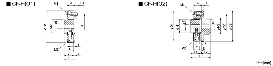
| Model | d1 | d2 | D1 | D2 | N1 | N2 | L1 | L2 | L3 | A | B | B1 | C | E | F | S | TK | M1 | M2 | ||||
|---|---|---|---|---|---|---|---|---|---|---|---|---|---|---|---|---|---|---|---|---|---|---|---|
| Pilot bore | Min. | Max. | Pilot bore | Min. | Max. | ||||||||||||||||||
| CF-H-008 | 12 | 14 | 38 | 15 | 16 | 46 | 125 | 120 | 60 | 70 | 40 | 42 | 88 | 32 | 10 | 10 | 46 | 25 | 20 | 6 | 100 | 3-M10 | 3-M10 |
| CF-H-016 | 15 | 16 | 48 | 19 | 20 | 56 | 155 | 150 | 70 | 85 | 52 | 50 | 110 | 41 | 12 | 12 | 60 | 34 | 26 | 8 | 125 | 3-M12 | 3-M12 |
| CF-H-030 | 20 | 22 | 65 | 28 | 30 | 80 | 205 | 200 | 100 | 120 | 68 | 66 | 144 | 56 | 16 | 15 | 78 | 46 | 35 | 10 | 165 | 3-M16 | 3-M16 |
| CF-H-040 | 22 | 24 | 50 | 22 | 24 | 65 | 175 | 180 | 85 | 100 | 58 | 56 | 124 | 50 | 16 | 16 | 68 | 42 | 31 | 10 | 140 | 4-M16 | 4-M16 |
| CF-H-050 | 20 | 22 | 65 | 28 | 30 | 80 | 205 | 200 | 100 | 120 | 68 | 66 | 144 | 56 | 16 | 15 | 78 | 46 | 35 | 10 | 165 | 4-M16 | 4-M16 |
| CF-H-090 | 20 | 22 | 65 | 28 | 30 | 80 | 215 | 200 | 100 | 120 | 68 | 66 | 144 | 56 | 16 | 15 | 78 | 46 | 35 | 10 | 165 | 4-M16 | 4-M16 |
| CF-H-110 | 25 | 28 | 63 | 28 | 30 | 80 | 225 | 230 | 100 | 120 | 68 | 66 | 144 | 56 | 18 | 18 | 78 | 46 | 35 | 10 | 180 | 4-M18 | 4-M18 |
| CF-H-160 | 30 | 32 | 85 | 30 | 32 | 95 | 270 | 260 | 125 | 140 | 84 | 80 | 177 | 59 | 19 | 20 | 97 | 48 | 37 | 13 | 215 | 4-M20 | 4-M20 |
| CF-H-240 | 40 | 42 | 115 | 40 | 42 | 120 | 330 | 320 | 160 | 180 | 100 | 100 | 213 | 65 | 19 | 20 | 113 | 54 | 40 | 13 | 260 | 4-M20 | 4-M20 |
*Pilot bores are to be drilled into the part. Minimum values for d1 and d2 are given by the minimum bore diameter values in the MIKI PULLEY standard hole-drilling standards and maximum values from the maximum allowable drilled bore diameters.
*The TK dimension is the bolt mounting pitch diameter of the fl ange hub or paired mounting part.

[Standard Hole-drilling Standards]
| Models compliant with the old JIS standard (class 2) JIS B 1301 1959 | Models compliant with the new JIS standard (H9) JIS B 1301 1996 | Models compliant with the motor standard JIS C 4210 2001 | ||||||||||||
|---|---|---|---|---|---|---|---|---|---|---|---|---|---|---|
| Nominal bore diameter | Bore diameter (d1, d2) | Keyway width (W1, W2) | Keyway height (T1, T2) | Set screw hole (M) | Nominal bore diameter | Bore diameter (d1, d2) | Keyway width (W1, W2) | Keyway height (T1, T2) | Set screw hole (M) | Nominal bore diameter | Bore diameter (d1, d2) | Keyway width (W1, W2) | Keyway height (T1, T2) | Set screw hole (M) |
| Tolerance H7 | Tolerance E9 | - | Tolerance H7 | Tolerance H9 | - | Tolerance G7, F7 | Tolerance H9 | - | ||||||
| 14 | 14+0.0180 | 5+0.050+0.020 | 16.0+0.30 | 2-M4 | 14H | 14+0.0180 | 5+0.0300 | 16.3+0.30 | 2-M4 | 14N | 14+0.024+0.006 | 5+0.0300 | 16.3+0.30 | 2-M4 |
| 15 | 15+0.0180 | 5+0.050+0.020 | 17.0+0.30 | 2-M4 | 15H | 15+0.0180 | 5+0.0300 | 17.3+0.30 | 2-M4 | - | - | - | - | - |
| 16 | 16+0.0180 | 5+0.050+0.020 | 18.0+0.30 | 2-M4 | 16H | 16+0.0180 | 5+0.0300 | 18.3+0.30 | 2-M4 | - | - | - | - | - |
| 17 | 17+0.0180 | 5+0.050+0.020 | 19.0+0.30 | 2-M4 | 17H | 17+0.0180 | 5+0.0300 | 19.3+0.30 | 2-M4 | - | - | - | - | - |
| 18 | 18+0.0180 | 5+0.050+0.020 | 20.0+0.30 | 2-M4 | 18H | 18+0.0180 | 6+0.0300 | 20.8+0.30 | 2-M5 | - | - | - | - | - |
| 19 | 19+0.0210 | 5+0.050+0.020 | 21.0+0.30 | 2-M4 | 19H | 19+0.0210 | 6+0.0300 | 21.8+0.30 | 2-M5 | 19N | 19+0.028+0.007 | 6+0.0300 | 21.8+0.30 | 2-M5 |
| 20 | 20+0.0210 | 5+0.050+0.020 | 22.0+0.30 | 2-M4 | 20H | 20+0.0210 | 6+0.0300 | 22.8+0.30 | 2-M5 | - | - | - | - | - |
| 22 | 22+0.0210 | 7+0.061+0.025 | 25.0+0.30 | 2-M6 | 22H | 22+0.0210 | 6+0.0300 | 24.8+0.30 | 2-M5 | - | - | - | - | - |
| 24 | 24+0.0210 | 7+0.061+0.025 | 27.0+0.30 | 2-M6 | 24H | 24+0.0210 | 8+0.0360 | 27.3+0.30 | 2-M6 | 24N | 24+0.028+0.007 | 8+0.0360 | 27.3+0.30 | 2-M6 |
| 25 | 25+0.0210 | 7+0.061+0.025 | 28.0+0.30 | 2-M6 | 25H | 25+0.0210 | 8+0.0360 | 28.3+0.30 | 2-M6 | - | - | - | - | - |
| 28 | 28+0.0210 | 7+0.061+0.025 | 31.0+0.30 | 2-M6 | 28H | 28+0.0210 | 8+0.0360 | 31.3+0.30 | 2-M6 | 28N | 28+0.028+0.007 | 8+0.0360 | 31.3+0.30 | 2-M6 |
| 30 | 30+0.0210 | 7+0.061+0.025 | 33.0+0.30 | 2-M6 | 30H | 30+0.0210 | 8+0.0360 | 33.3+0.30 | 2-M6 | - | - | - | - | - |
| 32 | 32+0.0250 | 10+0.061+0.025 | 35.5+0.30 | 2-M8 | 32H | 32+0.0250 | 10+0.0360 | 35.3+0.30 | 2-M8 | - | - | - | - | - |
| 35 | 35+0.0250 | 10+0.061+0.025 | 38.5+0.30 | 2-M8 | 35H | 35+0.0250 | 10+0.0360 | 38.3+0.30 | 2-M8 | - | - | - | - | - |
| 38 | 38+0.0250 | 10+0.061+0.025 | 41.5+0.30 | 2-M8 | 38H | 38+0.0250 | 10+0.0360 | 41.3+0.30 | 2-M8 | 38N | 38+0.050+0.025 | 10+0.0360 | 41.3+0.30 | 2-M8 |
| 40 | 40+0.0250 | 10+0.061+0.025 | 43.5+0.30 | 2-M8 | 40H | 40+0.0250 | 12+0.0430 | 43.3+0.30 | 2-M8 | - | - | - | - | - |
| 42 | 42+0.0250 | 12+0.075+0.032 | 45.5+0.30 | 2-M8 | 42H | 42+0.0250 | 12+0.0430 | 45.3+0.30 | 2-M8 | 42N | 42+0.050+0.025 | 12+0.0430 | 45.3+0.30 | 2-M8 |
| 45 | 45+0.0250 | 12+0.075+0.032 | 48.5+0.30 | 2-M8 | 45H | 45+0.0250 | 14+0.0430 | 48.8+0.30 | 2-M10 | - | - | - | - | - |
| 48 | 48+0.0250 | 12+0.075+0.032 | 51.5+0.30 | 2-M8 | 48H | 48+0.0250 | 14+0.0430 | 51.8+0.30 | 2-M10 | 48N | 48+0.050+0.025 | 14+0.0430 | 51.8+0.30 | 2-M10 |
| 50 | 50+0.0250 | 12+0.075+0.032 | 53.5+0.30 | 2-M8 | 50H | 50+0.0250 | 14+0.0430 | 53.8+0.30 | 2-M10 | - | - | - | - | - |
| 55 | 55+0.0300 | 15+0.075+0.032 | 60.0+0.30 | 2-M10 | 55H | 55+0.0300 | 16+0.0430 | 59.3+0.30 | 2-M10 | 55N | 55+0.060+0.030 | 16+0.0430 | 59.3+0.30 | 2-M10 |
| 56 | 56+0.0300 | 15+0.075+0.032 | 61.0+0.30 | 2-M10 | 56H | 56+0.0300 | 16+0.0430 | 60.3+0.30 | 2-M10 | - | - | - | - | - |
| 60 | 60+0.0300 | 15+0.075+0.032 | 65.0+0.30 | 2-M10 | 60H | 60+0.0300 | 18+0.0430 | 64.4+0.30 | 2-M10 | 60N | 60+0.060+0.030 | 18+0.0430 | 64.4+0.30 | 2-M10 |
| 63 | 63+0.0300 | 18+0.075+0.032 | 69.0+0.30 | 2-M10 | 18H | 63+0.0300 | 18+0.0430 | 67.4+0.30 | 2-M10 | - | - | - | - | - |
| 65 | 65+0.0300 | 18+0.075+0.032 | 71.0+0.30 | 2-M10 | 65H | 65+0.0300 | 18+0.0430 | 69.4+0.30 | 2-M10 | 65N | 65+0.060+0.030 | 18+0.0430 | 69.4+0.30 | 2-M10 |
*Positions of set screws and keyways are not on the same plane.
*Set screws are included with the product.
*Positioning precision for keyway milling is determined by sight.
*Contact Miki Pulley when the keyway requires a positioning precision for a particular flange hub.
*Consult the technical documentation at the end of this volume for standard dimensions for bore drilling other than those given here.
*We can also machine splines. Please contact Miki Pulley.
[Set screw position (Cylinder hub)]
| Cylindrical hub coupling size | Distance from edge[mm] |
|---|---|
| 008 | 7 |
| 016 | 10 |
| 030 | 11 |
| 040 | 10 |
| 050・090・110 | 11 |
| 160・240 | 15 |
[Set screw position (Flange hub)]
| Flange hub coupling size | Distance from edge[mm] |
|---|---|
| 008 | 9 |
| 016 | 10 |
| 030 | 15 |
| 040 | 10 |
| 050・090・110 | 15 |
| 160・240 | 15 |
CF-H