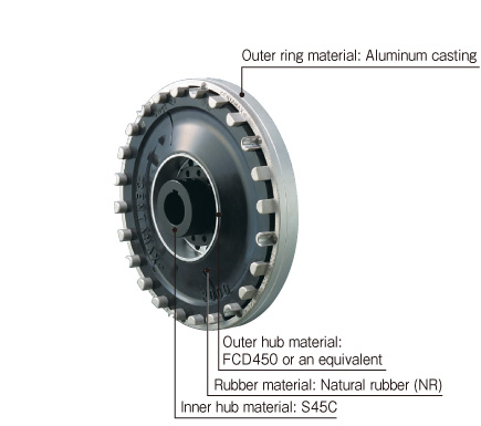
These are couplings for engines that transmit power using highly elastic rubber and are excellent at absorbing vibration and shock. They are very soft in the bending direction, and are able to escape the resonance point caused by torsional vibration at or below engine low idle.Being short in the axial direction, they do not require space and can easily engage or isolate input/output simply by moving in the axial direction, facilitating maintenance.
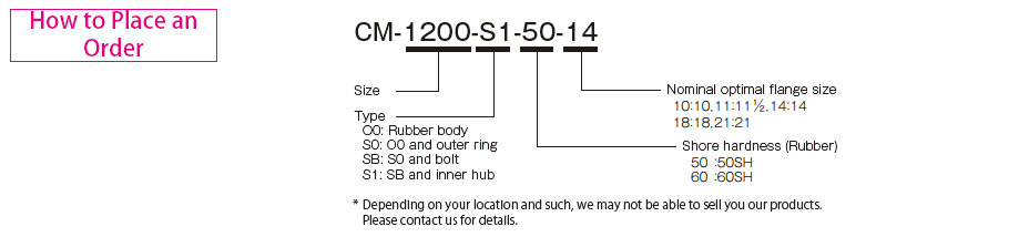
CM Models,*Made to order
[Specifications]
| Model | Shore hardness 50SH Torque | Shore hardness 50SH Dynamic torsional stiffness [N・m/rad] | Shore hardness 60SH Torque | Shore hardness 60SH Dynamic torsional stiffness [N・m/rad] | Misalignment | Max. rotation speed [min-1] | Compatible flange size SAE J620 | ||||||
|---|---|---|---|---|---|---|---|---|---|---|---|---|---|
| Nominal [N・m] | Max. [N・m] | Continuous vibration torque [N・m/10Hz] | Nominal [N・m] | Max. [N・m] | Continuous vibration torque [N・m/10Hz] | Parallel [mm] | Angular [°] | ||||||
| CM-800-S1 | 700 | 1400 | 280 | 2.80×10³ | 850 | 1700 | 340 | 4.20×10³ | 0.5 | 0.5 | 3600 | 10・11 1/2・14 | |
| CM-1200-S1 | 1000 | 2000 | 400 | 4.50×10³ | 1200 | 2400 | 480 | 7.00×10³ | 0.5 | 0.5 | 3500 | 11 1/2・14 | |
| CM-2400-S1 | 2000 | 4000 | 800 | 1.00×10⁴ | 2500 | 5000 | 1000 | 1.50×10⁴ | 0.5 | 0.5 | 3000 | 14 | |
| CM-2800-S1 | 2800 | 6000 | 1120 | 2.50×10⁴ | 3000 | 7500 | 1200 | 3.75×10⁴ | 0.5 | 0.5 | 3000 | 14 | |
| CM-3000-S1 | 3000 | 6000 | 1200 | 1.00×10⁴ | 3300 | 7000 | 1300 | 1.51×10⁴ | 0.5 | 0.5 | 3000 | 14・18 | |
| CM-3500-S1 | 3200 | 6500 | 1280 | 1.60×10⁴ | 3500 | 8000 | 1400 | 2.40×10⁴ | 0.5 | 0.5 | 3000 | 14・18 | |
| CM-4000-S1 | - | - | - | - | 4500 | 11000 | 1800 | 5.00×10⁴ | 0.5 | 0.5 | 3000 | 14・18 | |
| CM-5000-S1 | 4500 | 9000 | 1800 | 1.70×10⁴ | 5000 | 10000 | 2000 | 2.70×10⁴ | 0.5 | 0.5 | 3000 | 14・18 | |
| CM-7000-S1 | 6300 | 12600 | 2520 | 2.85×10⁴ | 7000 | 14000 | 2800 | 4.50×10⁴ | 0.5 | 0.5 | 2500 | 18 | |
| CM-8000-S1 | - | - | - | - | 9000 | 22000 | 3600 | 8.00×10⁴ | 0.5 | 0.5 | 2500 | 18・21 | |
| CM-18000-S1 | 16000 | 32000 | 6400 | 1.15×10⁵ | 18000 | 36000 | 7200 | 1.70×10⁵ | 0.5 | 0.5 | 2300 | 21 | |
*Max. rotation speed is for the minimum flange size.This also does not take into account dynamic balance.
[Dimensions]
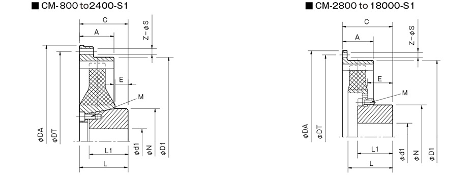
| Model | Compatible flange size SAE J620 | A | C | d1 | D1 | E | L | L1 | N | M | |
|---|---|---|---|---|---|---|---|---|---|---|---|
| Pilot bore | Max. | ||||||||||
| CM-800 | 10 | 50 | 82±2 | 18 | 70 | 316 | 18 | 84 | 66 | 107 | 8-M10 |
| 111/2 | 39 | 71±3 | 18 | 70 | 318 | 18 | 84 | 66 | 107 | 8-M10 | |
| 14 | 46 | 74±6 | 18 | 70 | 318 | 18 | 84 | 66 | 107 | 8-M10 | |
| CM-1200 | 111/2 | 39 | 65±4 | 18 | 70 | 318 | 18 | 84 | 66 | 107 | 8-M10 |
| 14 | 46 | 74±1 | 18 | 70 | 318 | 18 | 84 | 66 | 107 | 8-M10 | |
| CM-2400 | 61 | 85+8-2 | 28 | 105 | 417 | 16 | 96 | 75 | 150 | 8-M12 | |
| CM-2800 | 61 | 130±4 | 33 | 110 | 417 | 71 | 126 | 100 | 162 | 8-M16 | |
| CM-3000 | 14・18 | 70 | 135±8 | 19 | 65 | 465 | 53 | 135 | 105 | 100 | 12-M12 |
| CM-3500 | 14・18 | 70 | 135±6 | 33 | 110 | 465 | 59 | 139 | 100 | 162 | 8-M16 |
| CM-4000 | 14・18 | 70 | 161±6 | 48 | 140 | 465 | 94 | 159 | 125 | 218 | 12-M16 |
| CM-5000 | 14・18 | 70 | 147±2 | 35 | 110 | 465 | 64 | 159 | 105 | 162 | 12-M16 |
| CM-7000 | 18 | 80 | 159±9 | 48 | 140 | 570 | 76 | 161 | 125 | 218 | 12-M16 |
| CM-8000 | 18 | 90 | 197±5 | 68 | 175 | 600 | 110 | 195 | 150 | 248 | 12-M20 |
| 21 | 197±5 | 68 | 175 | 584 | 110 | 195 | 150 | 248 | 12-M20 | ||
| CM-18000 | 141 | 310±9 | 70 | 680 | 176 | 306 | 200 | 24-M20 | |||
*The dimensions of the outer ring on the drive side are for mounting directly on an SAE J620 flywheel.