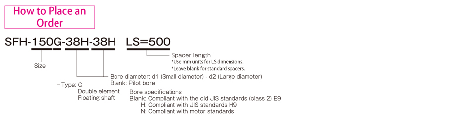
The maximum size with disc spring couplings for high-output applications is an outer flange diameter of 262 mm and rated torque of 8000 N・m. Single-element types with high torsional stiffness and flexible double-element floating-shaft types that connect double elements with an intermediate floating shaft are available. The floating shaft is particularly able to handle the setting of lengths according to customer requirements.
Choose your own mounting system
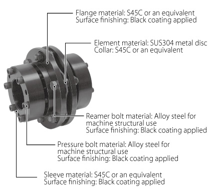
Can be assembled from part components
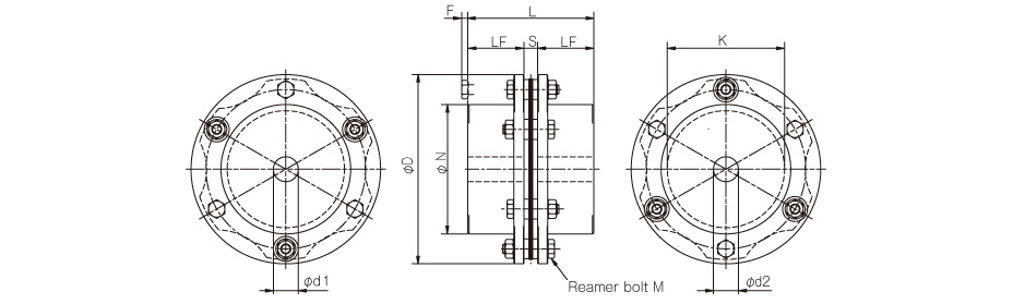
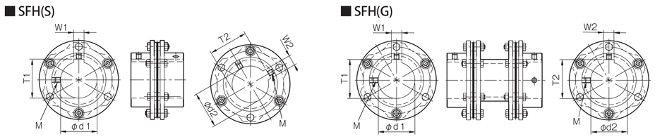
SFH (S) Types
[Specifications] SFH-□S
| Model | Rated torque [N・m] | Misalignment | Max. rotation speed [min-1] | Torsional stiffness [N・m/rad] | Axial stiffness[N/mm] | Moment of inertia [kg・m2] | Mass [kg] | |
|---|---|---|---|---|---|---|---|---|
| Angular [°] | Axial [mm] | |||||||
| SFH-150S | 1000 | 1 | ±0.4 | 5900 | 1500000 | 244 | 12.60×10⁻³ | 4.71 |
| SFH-170S | 1300 | 1 | ±0.5 | 5100 | 2840000 | 224 | 26.88×10⁻³ | 7.52 |
| SFH-190S | 2000 | 1 | ±0.5 | 4700 | 3400000 | 244 | 43.82×10⁻³ | 10.57 |
| SFH-210S | 4000 | 1 | ±0.55 | 4300 | 4680000 | 508 | 68.48×10⁻³ | 13.78 |
| SFH-220S | 5000 | 1 | ±0.6 | 4000 | 5940000 | 448 | 102.53×10⁻³ | 18.25 |
| SFH-260S | 8000 | 1 | ±0.7 | 3400 | 10780000 | 612 | 233.86×10⁻³ | 29.66 |
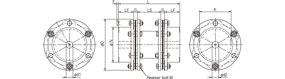
[Dimensions] SFH-□S
| Model | d1, d2 | D | N | L | LF | S | F | K | M | ||
|---|---|---|---|---|---|---|---|---|---|---|---|
| Pilot bore | Min. | Max. | |||||||||
| SFH-150S | 20 | 22 | 70 | 152 | 104 | 101 | 45 | 11 | 5 | 94 | 6-M8×36 |
| SFH-170S | 25 | 28 | 80 | 178 | 118 | 124 | 55 | 14 | 6 | 108 | 6-M10×45 |
| SFH-190S | 30 | 32 | 85 | 190 | 126 | 145 | 65 | 15 | 10 | 116 | 6-M12×54 |
| SFH-210S | 35 | 38 | 90 | 210 | 130 | 165 | 75 | 15 | 8 | 124 | 6-M16×60 |
| SFH-220S | 45 | 48 | 100 | 225 | 144 | 200 | 90 | 20 | -2 | 132 | 6-M16×60 |
| SFH-260S | 50 | 55 | 115 | 262 | 166 | 223 | 100 | 23 | 11 | 150 | 6-M20×80 |

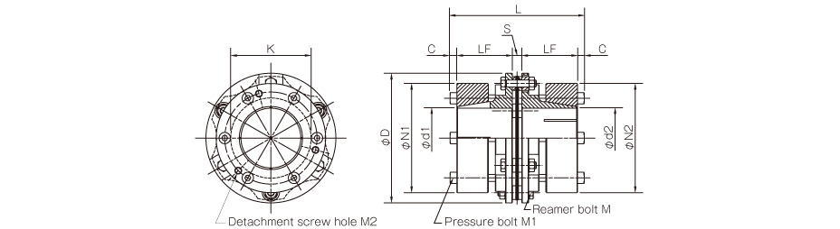
[Specifications] SFH-□S-□K-□K
| Model | Rated torque [N・m] | Misalignment | Max. rotation speed [min-1] | Torsional stiffness [N・m/rad] | Axial stiffness[N/mm] | Moment of inertia [kg・m2] | Mass [kg] | |
|---|---|---|---|---|---|---|---|---|
| Angular [°] | Axial [mm] | |||||||
| SFH-150S | 1000 | 1 | ±0.4 | 5900 | 1500000 | 244 | 25.14×10⁻³ | 8.95 |
| SFH-170S | 1300 | 1 | ±0.5 | 5100 | 2840000 | 224 | 47.90×10⁻³ | 12.53 |
| SFH-190S | 2000 | 1 | ±0.5 | 4700 | 3400000 | 244 | 60.40×10⁻³ | 14.21 |
| SFH-210S | 4000 | 1 | ±0.55 | 4300 | 4680000 | 508 | 80.50×10⁻³ | 16.12 |
[Dimensions] SFH-□S-□K-□K
| Model | D | L | d1, d2 | N1, N2 | LF | S | C | K | M | M1 | M2 |
|---|---|---|---|---|---|---|---|---|---|---|---|
| SFH-150S | 152 | 157 | 38, 40, 42, 45, 48, 50 | 108 | 65 | 11 | 8 | 94 | 6-M8×36 | 6-M8×60 | 3-M8 |
| 55, 56, 60, 65, 70 | 128 | ||||||||||
| SFH-170S | 178 | 160 | 38, 40, 42, 45, 48, 50 | 108 | 65 | 14 | 8 | 108 | 6-M10×45 | 6-M8×60 | 3-M8 |
| 55, 56, 60, 65, 70 | 128 | ||||||||||
| 75, 80 | 148 | ||||||||||
| SFH-190S | 190 | 175 | 38, 40, 42, 45, 48, 50 | 108 | 70 | 15 | 10 | 116 | 6-M12×54 | 6-M10×65 | 3-M10 |
| 55, 56, 60, 65, 70 | 128 | ||||||||||
| 75, 80, 85 | 148 | ||||||||||
| SFH-210S | 210 | 181 | 38, 40, 42, 45, 48, 50 | 108 | 73 | 15 | 10 | 124 | 6-M16×60 | 6-M10×65 | 3-M10 |
| 55, 56, 60, 65, 70 | 128 | ||||||||||
| 75, 80, 85, 90 | 148 |
[Standard bore diameter combinations]
| Model | Standard bore diameters d1, d2 [mm] | ||||||||||||||
|---|---|---|---|---|---|---|---|---|---|---|---|---|---|---|---|
| 38 | 40 | 42 | 45 | 48 | 50 | 55 | 56 | 60 | 65 | 70 | 75 | 80 | 85 | 90 | |
| SFH-150S | ● | ● | ● | ● | ● | ● | ● | ● | ● | ● | ● | ||||
| SFH-170S | 1100 | 1200 | 1250 | ● | ● | ● | ● | ● | ● | ● | ● | ● | ● | ||
| SFH-190S | 1800 | 1900 | ● | ● | ● | ● | ● | ● | ● | ● | ● | ● | ● | ● | |
| SFH-210S | 1800 | 1900 | 2000 | 2150 | 2300 | 2400 | 2600 | 2650 | 2850 | 3100 | 3350 | 3600 | 3800 | ● | ● |

[Standard Hole-drilling Standards]
| Models compliant with the old JIS standard (class 2) JIS B 1301 1959 | Models compliant with the new JIS standard (H9) JIS B 1301 1996 | Models compliant with the motor standard JIS C 4210 2001 | ||||||||||||
|---|---|---|---|---|---|---|---|---|---|---|---|---|---|---|
| Nominal bore diameter | Bore diameter (d1, d2) | Keyway width (W1, W2) | Keyway height (T1, T2) | Set screw hole (M) | Nominal bore diameter | Bore diameter (d1, d2) | Keyway width (W1, W2) | Keyway height (T1, T2) | Set screw hole (M) | Nominal bore diameter | Bore diameter (d1, d2) | Keyway width (W1, W2) | Keyway height (T1, T2) | Set screw hole (M) |
| ToleranceH7 | ToleranceE9 | -- | -- | ToleranceH7 | ToleranceH9 | -- | -- | ToleranceG7, F7 | ToleranceH9 | -- | -- | |||
| 22 | 22+0.0210 | 7+0.061+0.025 | 25.0+0.30 | 2-M6 | 22H | 22+0.0210 | 6+0.0300 | 24.8+0.30 | 2-M5 | -- | -- | -- | -- | -- |
| 24 | 24+0.0210 | 7+0.061+0.025 | 27.0+0.30 | 2-M6 | 24H | 24+0.0210 | 8+0.0360 | 27.3+0.30 | 2-M6 | 24N | 24+0.028+0.007 | 8+0.0360 | 27.3+0.30 | 2-M6 |
| 25 | 25+0.0210 | 7+0.061+0.025 | 28.0+0.30 | 2-M6 | 25H | 25+0.0210 | 8+0.0360 | 28.3+0.30 | 2-M6 | -- | -- | -- | -- | -- |
| 28 | 28+0.0210 | 7+0.061+0.025 | 31.0+0.30 | 2-M6 | 28H | 28+0.0210 | 8+0.0360 | 31.3+0.30 | 2-M6 | 28N | 28+0.028+0.007 | 8+0.0360 | 31.3+0.30 | 2-M6 |
| 30 | 30+0.0210 | 7+0.061+0.025 | 33.0+0.30 | 2-M6 | 30H | 30+0.0210 | 8+0.0360 | 33.3+0.30 | 2-M6 | -- | -- | -- | -- | -- |
| 32 | 32+0.0250 | 10+0.061+0.025 | 35.5+0.30 | 2-M8 | 32H | 32+0.0250 | 10+0.0360 | 35.3+0.30 | 2-M8 | -- | -- | -- | -- | -- |
| 35 | 35+0.0250 | 10+0.061+0.025 | 38.5+0.30 | 2-M8 | 35H | 35+0.0250 | 10+0.0360 | 38.3+0.30 | 2-M8 | -- | -- | -- | -- | -- |
| 38 | 38+0.0250 | 10+0.061+0.025 | 41.5+0.30 | 2-M8 | 38H | 38+0.0250 | 10+0.0360 | 41.3+0.30 | 2-M8 | 38N | 38+0.050+0.025 | +0.036010 | 41.3+0.30 | 2-M8 |
| 40 | 40+0.0250 | 10+0.061+0.025 | 43.5+0.30 | 2-M8 | 40H | 40+0.0250 | 12+0.0430 | 43.3+0.30 | 2-M8 | -- | -- | -- | -- | -- |
| 42 | 42+0.0250 | 12+0.061+0.025 | 45.5+0.30 | 2-M8 | 42H | 42+0.0250 | 12+0.0430 | 45.3+0.30 | 2-M8 | 42N | 42+0.050+0.025 | 12+0.0430 | 45.3+0.30 | 2-M8 |
| 45 | 45+0.0250 | 12+0.061+0.025 | 48.5+0.30 | 2-M8 | 45H | 45+0.0250 | 14+0.0430 | 48.8+0.30 | 2-M10 | -- | -- | -- | -- | -- |
| 48 | 48+0.0250 | 12+0.061+0.025 | 51.5+0.30 | 2-M8 | 48H | 48+0.0250 | 14+0.0430 | 51.8+0.30 | 2-M10 | 48N | 48+0.050+0.025 | 14+0.0430 | 51.8+0.30 | 2-M10 |
| 50 | 50+0.0250 | 12+0.061+0.025 | 53.5+0.30 | 2-M8 | 50H | 50+0.0250 | 14+0.0430 | 53.8+0.30 | 2-M10 | -- | -- | -- | -- | -- |
| 55 | 55+0.0300 | 15+0.075+0.032 | 60.0+0.30 | 2-M10 | 55H | 55+0.0300 | 16+0.0430 | 59.3+0.30 | 2-M10 | 55N | 55+0.060+0.030 | 16+0.0430 | 59.3+0.30 | 2-M10 |
| 56 | 56+0.0300 | 15+0.075+0.032 | 61.0+0.30 | 2-M10 | 56H | 56+0.0300 | 16+0.0430 | 60.3+0.30 | 2-M10 | -- | -- | -- | -- | -- |
| 60 | 60+0.0300 | 15+0.075+0.032 | 65.0+0.30 | 2-M10 | 60H | 60+0.0300 | 18+0.0430 | 64.4+0.30 | 2-M10 | 60N | 60+0.060+0.030 | 18+0.0430 | 64.4+0.30 | 2-M10 |
| 65 | 65+0.0300 | 18+0.075+0.032 | 71.0+0.30 | 2-M10 | 65H | 65+0.0300 | 18+0.0430 | 69.4+0.30 | 2-M10 | 65N | 65+0.060+0.030 | 18+0.0430 | 69.4+0.30 | 2-M10 |
| 70 | 70+0.0300 | 18+0.075+0.032 | 76.0+0.30 | 2-M10 | 70H | 70+0.0300 | 20+0.0520 | 74.9+0.50 | 2-M10 | -- | -- | -- | -- | -- |
| 75 | 75+0.0300 | 20+0.092+0.040 | 81.0+0.50 | 2-M10 | 75H | 75+0.0300 | 20+0.0520 | 79.9+0.50 | 2-M10 | 75N | 75+0.060+0.030 | 20+0.0520 | 79.9+0.50 | 2-M10 |
| 80 | 80+0.0300 | 20+0.092+0.040 | 86.0+0.50 | 2-M10 | 80H | 80+0.0300 | 22+0.0520 | 85.4+0.50 | 2-M12 | -- | -- | -- | -- | -- |
| 85 | 85+0.0350 | 24+0.092+0.040 | 93.0+0.50 | 2-M12 | 85H | 85+0.0350 | 22+0.0520 | 90.4+0.50 | 2-M12 | 85N | 85+0.071+0.035 | 22+0.0520 | 90.4+0.50 | 2-M12 |
| 90 | 90+0.0350 | 24+0.092+0.040 | 98.0+0.50 | 2-M12 | 90H | 90+0.0350 | 25+0.0520 | 95.4+0.50 | 2-M12 | -- | -- | -- | -- | -- |
| 95 | 95+0.0350 | 24+0.092+0.040 | 103.0+0.50 | 2-M12 | 95H | 95+0.0350 | 25+0.0520 | 100.4+0.50 | 2-M12 | 95N | 95+0.071+0.035 | 25+0.0520 | 100.4+0.50 | 2-M12 |
| 100 | 100+0.0350 | 28+0.092+0.040 | 109.0+0.50 | 2-M12 | 100H | 100+0.0350 | 28+0.0520 | 106.4+0.50 | 2-M12 | -- | -- | -- | -- | -- |
| 115 | 115+0.0350 | 32+0.112+0.050 | 125.0+0.50 | 2-M12 | 115H | 115+0.0350 | 32+0.0520 | 122.4+0.50 | 2-M12 | -- | -- | -- | -- | -- |
【Set screw position】
| Model | Distance from edge[mm] |
|---|---|
| SFH-150 | 15 |
| SFH-170 | 20 |
| SFH-190 | 25 |
| SFH-210 | 30 |
| SFH-220 | 35 |
| SFH-260 | 40 |
SFH (G) Types
[Specifications] SFH-□G
| Model | Rated torque [N・m] | Misalignment | Max. rotation speed [min-1] | Torsional stiffness [N・m/rad] | Axial stiffness[N/mm] | Moment of inertia [kg・m2] | Mass [kg] | ||
|---|---|---|---|---|---|---|---|---|---|
| Parallel [mm] | Angular [°] | Axial [mm] | |||||||
| SFH-150G | 1000 | 1.4 | 1 (On one side) | ±0.8 | 5900 | 750000 | 122 | 21.87×10⁻³ | 8.72 |
| SFH-170G | 1300 | 1.6 | 1 (On one side) | ±1.0 | 5100 | 1420000 | 112 | 51.07×10⁻³ | 13.94 |
| SFH-190G | 2000 | 2.0 | 1 (On one side) | ±1.0 | 4700 | 1700000 | 122 | 81.58×10⁻³ | 19.51 |
| SFH-210G | 4000 | 2.1 | 1 (On one side) | ±1.1 | 4300 | 2340000 | 254 | 125.50×10⁻³ | 24.26 |
| SFH-220G | 5000 | 2.3 | 1 (On one side) | ±1.2 | 4000 | 2970000 | 224 | 176.91×10⁻³ | 30.27 |
| SFH-260G | 8000 | 2.9 | 1 (On one side) | ±1.4 | 3400 | 5390000 | 306 | 433.47×10⁻³ | 53.11 |
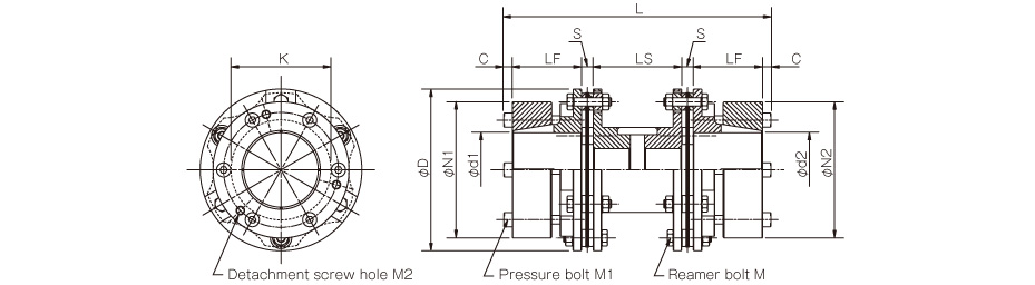
[Dimensions] SFH-□G
| Model | d1, d2 | D | N | L | LF | LS | S | F | K | M | ||
|---|---|---|---|---|---|---|---|---|---|---|---|---|
| Pilot bore | Min. | Max. | ||||||||||
| SFH-150G | 20 | 22 | 70 | 152 | 104 | 182 | 45 | 70 | 11 | 5 | 94 | 12-M8×36 |
| SFH-170G | 25 | 28 | 80 | 178 | 118 | 218 | 55 | 80 | 14 | 6 | 108 | 12-M10×45 |
| SFH-190G | 30 | 32 | 85 | 190 | 126 | 260 | 65 | 100 | 15 | 10 | 116 | 12-M12×54 |
| SFH-210G | 35 | 38 | 90 | 210 | 130 | 290 | 75 | 110 | 15 | 8 | 124 | 12-M16×60 |
| SFH-220G | 45 | 48 | 100 | 225 | 144 | 335 | 90 | 115 | 20 | -2 | 132 | 12-M16×60 |
| SFH-260G | 50 | 55 | 115 | 262 | 166 | 391 | 100 | 145 | 23 | 11 | 150 | 12-M20×80 |
[Dimensions for Vertical Applications with Max. LS Dimensions] SFH-□G-□K-□K
| Model | LS [mm] |
|---|---|
| SFH-150G | 1100 |
| SFH-170G | 800 |
| SFH-190G | 900 |
| SFH-210G | 2000 |
| SFH-220G | 1900 |
| SFH-260G | 2500 |
[Specifications] SFH-□G-□K-□K
| Model | Rated torque [N・m] | Misalignment | Max. rotation speed [min-1] | Torsional stiffness ([N・m]/rad) | Axial stiffness[N/mm] | Moment of inertia [kg・m2] | Mass [kg] | ||
|---|---|---|---|---|---|---|---|---|---|
| Parallel [mm] | Angular [°] | Axial [mm] | |||||||
| SFH-150G | 1000 | 1.4 | 1 (On one side) | ±0.8 | 5900 | 750000 | 122 | 34.41×10⁻³ | 12.96 |
| SFH-170G | 1300 | 1.6 | 1 (On one side) | ±1.0 | 5100 | 1420000 | 112 | 72.09×10⁻³ | 18.95 |
| SFH-190G | 2000 | 2.0 | 1 (On one side) | ±1.0 | 4700 | 1700000 | 122 | 98.15×10⁻³ | 23.14 |
| SFH-210G | 4000 | 2.1 | 1 (On one side) | ±1.1 | 4300 | 2340000 | 254 | 137.53×10⁻³ | 26.61 |
[Dimensions] SFH-□G-□K-□K
| Model | D | L | d1, d2 | N1, N2 | LF | LS | S | C | K | M | M1 | M2 |
|---|---|---|---|---|---|---|---|---|---|---|---|---|
| SFH-150G | 152 | 238 | 38, 40, 42, 45, 48, 50 | 108 | 65 | 70 | 11 | 8 | 94 | 12-M8×36 | 6-M8×60 | 3-M8 |
| 55, 56, 60, 65, 70 | 128 | |||||||||||
| SFH-170G | 178 | 254 | 38, 40, 42, 45, 48, 50 | 108 | 65 | 80 | 14 | 8 | 108 | 12-M10×45 | 6-M8×60 | 3-M8 |
| 55, 56, 60, 65, 70 | 128 | |||||||||||
| 75, 80 | 148 | |||||||||||
| SFH-190G | 190 | 290 | 38, 40, 42, 45, 48, 50 | 108 | 70 | 100 | 15 | 10 | 116 | 12-M12×54 | 6-M10×65 | 3-M10 |
| 55, 56, 60, 65, 70 | 128 | |||||||||||
| 75, 80, 85 | 148 | |||||||||||
| SFH-210G | 210 | 306 | 38, 40, 42, 45, 48, 50 | 108 | 73 | 110 | 15 | 10 | 124 | 12-M16×60 | 6-M10×65 | 3-M10 |
| 55, 56, 60, 65, 70 | 128 | |||||||||||
| 75, 80, 85, 90 | 148 |
[Combination of Standard Bore Diameter]
| Model | Standard bore diameters d1, d2 [mm] | ||||||||||||||
|---|---|---|---|---|---|---|---|---|---|---|---|---|---|---|---|
| 38 | 40 | 42 | 45 | 48 | 50 | 55 | 56 | 60 | 65 | 70 | 75 | 80 | 85 | 90 | |
| SFH-150G | ● | ● | ● | ● | ● | ● | ● | ● | ● | ● | ● | ||||
| SFH-170G | 1100 | 1200 | 1250 | ● | ● | ● | ● | ● | ● | ● | ● | ● | ● | ||
| SFH-190G | 1800 | 1900 | ● | ● | ● | ● | ● | ● | ● | ● | ● | ● | ● | ● | |
| SFH-210G | 1800 | 1900 | 2000 | 2150 | 2300 | 2400 | 2600 | 2650 | 2850 | 3100 | 3350 | 3600 | 3800 | ● | ● |
[Dimensions for Vertical Applications with Max. LS Dimensions]
| Model | LS [mm] |
|---|---|
| SFH-150G | 1100 |
| SFH-170G | 800 |
| SFH-190G | 900 |
| SFH-210G | 2000 |
[Standard Hole-drilling Standards]
| Models compliant with the old JIS standard (class 2) JIS B 1301 1959 | Models compliant with the new JIS standard (H9) JIS B 1301 1996 | Models compliant with the motor standard JIS C 4210 2001 | ||||||||||||
|---|---|---|---|---|---|---|---|---|---|---|---|---|---|---|
| Nominal bore diameter | Bore diameter (d1, d2) | Keyway width (W1, W2) | Keyway height (T1, T2) | Set screw hole (M) | Nominal bore diameter | Bore diameter (d1, d2) | Keyway width (W1, W2) | Keyway height (T1, T2) | Set screw hole (M) | Nominal bore diameter | Bore diameter (d1, d2) | Keyway width (W1, W2) | Keyway height (T1, T2) | Set screw hole (M) |
| ToleranceH7 | ToleranceE9 | -- | -- | ToleranceH7 | ToleranceH9 | -- | -- | ToleranceG7, F7 | ToleranceH9 | -- | -- | |||
| 22 | 22+0.0210 | 7+0.061+0.025 | 25.0+0.30 | 2-M6 | 22H | 22+0.0210 | 6+0.0300 | 24.8+0.30 | 2-M5 | -- | -- | -- | -- | -- |
| 24 | 24+0.0210 | 7+0.061+0.025 | 27.0+0.30 | 2-M6 | 24H | 24+0.0210 | 8+0.0360 | 27.3+0.30 | 2-M6 | 24N | 24+0.028+0.007 | 8+0.0360 | 27.3+0.30 | 2-M6 |
| 25 | 25+0.0210 | 7+0.061+0.025 | 28.0+0.30 | 2-M6 | 25H | 25+0.0210 | 8+0.0360 | 28.3+0.30 | 2-M6 | -- | -- | -- | -- | -- |
| 28 | 28+0.0210 | 7+0.061+0.025 | 31.0+0.30 | 2-M6 | 28H | 28+0.0210 | 8+0.0360 | 31.3+0.30 | 2-M6 | 28N | 28+0.028+0.007 | 8+0.0360 | 31.3+0.30 | 2-M6 |
| 30 | 30+0.0210 | 7+0.061+0.025 | 33.0+0.30 | 2-M6 | 30H | 30+0.0210 | 8+0.0360 | 33.3+0.30 | 2-M6 | -- | -- | -- | -- | -- |
| 32 | 32+0.0250 | 10+0.061+0.025 | 35.5+0.30 | 2-M8 | 32H | 32+0.0250 | 10+0.0360 | 35.3+0.30 | 2-M8 | -- | -- | -- | -- | -- |
| 35 | 35+0.0250 | 10+0.061+0.025 | 38.5+0.30 | 2-M8 | 35H | 35+0.0250 | 10+0.0360 | 38.3+0.30 | 2-M8 | -- | -- | -- | -- | -- |
| 38 | 38+0.0250 | 10+0.061+0.025 | 41.5+0.30 | 2-M8 | 38H | 38+0.0250 | 10+0.0360 | 41.3+0.30 | 2-M8 | 38N | 38+0.050+0.025 | +0.036010 | 41.3+0.30 | 2-M8 |
| 40 | 40+0.0250 | 10+0.061+0.025 | 43.5+0.30 | 2-M8 | 40H | 40+0.0250 | 12+0.0430 | 43.3+0.30 | 2-M8 | -- | -- | -- | -- | -- |
| 42 | 42+0.0250 | 12+0.061+0.025 | 45.5+0.30 | 2-M8 | 42H | 42+0.0250 | 12+0.0430 | 45.3+0.30 | 2-M8 | 42N | 42+0.050+0.025 | 12+0.0430 | 45.3+0.30 | 2-M8 |
| 45 | 45+0.0250 | 12+0.061+0.025 | 48.5+0.30 | 2-M8 | 45H | 45+0.0250 | 14+0.0430 | 48.8+0.30 | 2-M10 | -- | -- | -- | -- | -- |
| 48 | 48+0.0250 | 12+0.061+0.025 | 51.5+0.30 | 2-M8 | 48H | 48+0.0250 | 14+0.0430 | 51.8+0.30 | 2-M10 | 48N | 48+0.050+0.025 | 14+0.0430 | 51.8+0.30 | 2-M10 |
| 50 | 50+0.0250 | 12+0.061+0.025 | 53.5+0.30 | 2-M8 | 50H | 50+0.0250 | 14+0.0430 | 53.8+0.30 | 2-M10 | -- | -- | -- | -- | -- |
| 55 | 55+0.0300 | 15+0.075+0.032 | 60.0+0.30 | 2-M10 | 55H | 55+0.0300 | 16+0.0430 | 59.3+0.30 | 2-M10 | 55N | 55+0.060+0.030 | 16+0.0430 | 59.3+0.30 | 2-M10 |
| 56 | 56+0.0300 | 15+0.075+0.032 | 61.0+0.30 | 2-M10 | 56H | 56+0.0300 | 16+0.0430 | 60.3+0.30 | 2-M10 | -- | -- | -- | -- | -- |
| 60 | 60+0.0300 | 15+0.075+0.032 | 65.0+0.30 | 2-M10 | 60H | 60+0.0300 | 18+0.0430 | 64.4+0.30 | 2-M10 | 60N | 60+0.060+0.030 | 18+0.0430 | 64.4+0.30 | 2-M10 |
| 65 | 65+0.0300 | 18+0.075+0.032 | 71.0+0.30 | 2-M10 | 65H | 65+0.0300 | 18+0.0430 | 69.4+0.30 | 2-M10 | 65N | 65+0.060+0.030 | 18+0.0430 | 69.4+0.30 | 2-M10 |
| 70 | 70+0.0300 | 18+0.075+0.032 | 76.0+0.30 | 2-M10 | 70H | 70+0.0300 | 20+0.0520 | 74.9+0.50 | 2-M10 | -- | -- | -- | -- | -- |
| 75 | 75+0.0300 | 20+0.092+0.040 | 81.0+0.50 | 2-M10 | 75H | 75+0.0300 | 20+0.0520 | 79.9+0.50 | 2-M10 | 75N | 75+0.060+0.030 | 20+0.0520 | 79.9+0.50 | 2-M10 |
| 80 | 80+0.0300 | 20+0.092+0.040 | 86.0+0.50 | 2-M10 | 80H | 80+0.0300 | 22+0.0520 | 85.4+0.50 | 2-M12 | -- | -- | -- | -- | -- |
| 85 | 85+0.0350 | 24+0.092+0.040 | 93.0+0.50 | 2-M12 | 85H | 85+0.0350 | 22+0.0520 | 90.4+0.50 | 2-M12 | 85N | 85+0.071+0.035 | 22+0.0520 | 90.4+0.50 | 2-M12 |
| 90 | 90+0.0350 | 24+0.092+0.040 | 98.0+0.50 | 2-M12 | 90H | 90+0.0350 | 25+0.0520 | 95.4+0.50 | 2-M12 | -- | -- | -- | -- | -- |
| 95 | 95+0.0350 | 24+0.092+0.040 | 103.0+0.50 | 2-M12 | 95H | 95+0.0350 | 25+0.0520 | 100.4+0.50 | 2-M12 | 95N | 95+0.071+0.035 | 25+0.0520 | 100.4+0.50 | 2-M12 |
| 100 | 100+0.0350 | 28+0.092+0.040 | 109.0+0.50 | 2-M12 | 100H | 100+0.0350 | 28+0.0520 | 106.4+0.50 | 2-M12 | -- | -- | -- | -- | -- |
| 115 | 115+0.0350 | 32+0.112+0.050 | 125.0+0.50 | 2-M12 | 115H | 115+0.0350 | 32+0.0520 | 122.4+0.50 | 2-M12 | -- | -- | -- | -- | -- |
【Set screw position】
| Model | Distance from edge[mm] |
|---|---|
| SFH-150 | 15 |
| SFH-170 | 20 |
| SFH-190 | 25 |
| SFH-210 | 30 |
| SFH-220 | 35 |
| SFH-260 | 40 |
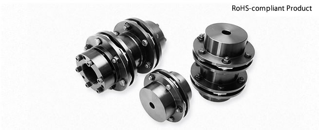
Lineup
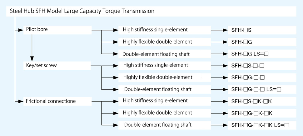
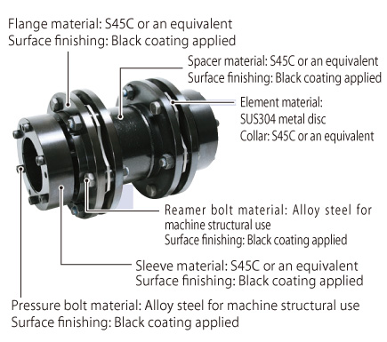
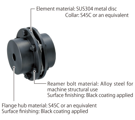
Structure and Materials
SFH S
SFH G
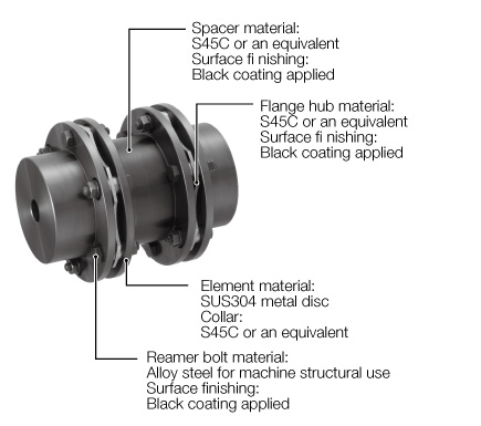
SFH S-□K-□K
SFH G-□K-□K